Mastering Predictive Maintenance with Vibration Sensors on Conveyor Drives
Learn how vibration sensors and predictive maintenance strategies reduce conveyor downtime by 35% and extend drive life through early fault detection and ISO standards.
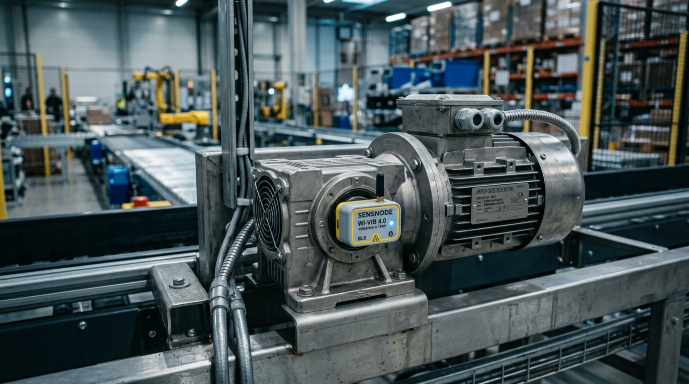
Predictive maintenance with vibration sensors on conveyor drives reduces unplanned downtime by up to 35% by detecting early-stage bearing failures and gear misalignments 3 to 6 months before catastrophic breakdown occurs. By shifting from reactive or scheduled maintenance to a condition-based approach, facilities can extend the operational life of drive components by approximately 20% while optimizing spare parts inventory through data-driven procurement.
Predictive maintenance (PdM) is no longer a luxury for high-end automotive plants; it has become a standard requirement for resilient supply chains. The core of this strategy lies in vibration analysis, which monitors the mechanical health of motors, gearboxes, and pulleys. In a modern modular conveyor system, a vibration sensor acts as the "stethoscope" of the machine, listening for the subtle high-frequency signals that precede heat, noise, and smoke.
The Fundamentals of Vibration Analysis in Conveyor Systems
Every rotating machine has a unique vibration signature. For conveyor drives, these signatures are influenced by the motor’s rotational speed, the number of teeth in the gearbox, and the frequency of the power supply. Predictive maintenance uses sensors—typically MEMS (Micro-Electro-Mechanical Systems) or piezoelectric accelerometers—to capture these vibrations in three axes (X, Y, and Z).
According to ISO 20816-1, vibration severity is measured through displacement, velocity, and acceleration. In conveyor applications, velocity (measured in mm/s RMS) is the most common metric for detecting general machine health issues, while high-frequency acceleration is used to pinpoint specific rolling element bearing defects.
Key Metrics for Conveyor Drive Monitoring:
- RMS Velocity: The overall energy of the vibration, indicating general imbalance or looseness.
- Peak-to-Peak Displacement: Used for low-speed shafts to detect misalignment.
- Crest Factor: A ratio of peak values to RMS, highly effective at spotting early bearing pitting.
Identifying Failure Modes Through Frequency Spectra
The power of vibration monitoring lies in the "Fast Fourier Transform" (FFT), a mathematical process that converts a time-domain signal into a frequency-domain spectrum. By analyzing specific frequencies, maintenance teams can distinguish between different mechanical problems.
- Imbalance: Typically manifests as a high peak at the 1x running speed of the motor.
- Misalignment: Often shows a strong signal at 2x the running speed, particularly in the axial direction.
- Bearing Wear: Produces high-frequency "harmonics" that appear long before the bearing starts to overheat.
- Gear Tooth Wear: Identified by "Gear Mesh Frequencies" (GMF), calculated by multiplying the number of teeth by the shaft's rotational speed.
Hardware Integration: MEMS vs. Piezoelectric Sensors
When selecting sensors for conveyor drives, engineers must choose between cost-effective MEMS sensors and high-precision piezoelectric transducers. For standard modular conveyors, MEMS sensors integrated with IO-Link or wireless protocols (like LoRaWAN) are increasingly popular due to their low cost and ease of installation.
| Feature | MEMS Sensors | Piezoelectric Sensors |
|---|---|---|
| Frequency Range | Up to 1-2 kHz | Up to 20+ kHz |
| Connectivity | Wireless/IO-Link | Analog (4-20mA / BNC) |
| Cost Tier | Low to Moderate | High |
| Power Consumption | Low (Battery capable) | Moderate (Wired) |
| Best Use Case | General conveyor health | High-speed, critical drives |
For facilities utilizing Easy Conveyors modules, integrating these sensors is simplified by the modular nature of the drive mounts. Whether using a drum motor or a standard gearmotor, the sensor should be placed as close to the load-bearing zone as possible—ideally on the bearing housing of the output shaft.
Easy Conveyors stocks the industrial automation discussed here — ready to ship across Europe.
Implementation: From Data to Actionable Insights
Successful predictive maintenance requires more than just installing hardware; it requires a data pipeline. Modern IEC 61131-3 compliant PLCs or dedicated edge gateways collect the raw data, filter out noise, and transmit it to a Centralized Maintenance Management System (CMMS).
Step 1: Establish a Baseline
You cannot identify an anomaly if you do not know what "normal" looks like. After installing a new drive or performing a major overhaul, the system should record vibration levels across various load conditions for 48 to 72 hours. This creates the baseline against which all future data is compared.
Step 2: Set Alarm Thresholds
Following standards like ISO 10816, thresholds are set for "Warning" (Yellow) and "Danger" (Red). If a conveyor drive exceeds these levels, the system automatically generates a work order.
Step 3: Automated Diagnosis
Advanced systems utilize AI-driven algorithms to correlate vibration spikes with other telemetry, such as motor current and temperature. For example, a spike in vibration combined with an increase in current often points to a mechanical jam or increased friction in the modular belt system.
Synergies with Other Automation Components
Vibration monitoring does not exist in a vacuum. To maximize the ROI, it should be paired with:
- VFD Soft-Start Tuning: Variable Frequency Drives can reduce the mechanical shock during startup, which lowers the baseline vibration levels and extends component life.
- Hygienic Wash-down Design: In food applications, sensors must meet EHEDG guidelines, featuring IP69K ratings to withstand high-pressure cleaning without signal degradation.
- Smart Lubrication: Automatic lubricators can be triggered by vibration analysis, ensuring that bearings receive grease exactly when the friction profile changes, rather than on a fixed calendar schedule.
The Economic Case for Predictive Maintenance
The initial investment in vibration sensors—typically ranging from €150 to €500 per drive point—is often recouped during the very first avoided failure. In high-volume e-commerce or automotive lines, the cost of downtime can exceed €1,000 per minute. By providing a 3-month lead time on a bearing replacement, the maintenance team can schedule the repair during a planned weekend shift, avoiding emergency shipping costs for parts and premium labor rates.
Furthermore, predictive maintenance aligns with IE3 and IE4 motor efficiency standards. A drive that is vibrating excessively due to misalignment is inherently inefficient, wasting energy as heat and sound. Correcting these issues ensures the conveyor operates at its peak rated efficiency, contributing to corporate sustainability goals.
Future Trends: The Edge and the Cloud
The next frontier for conveyor predictive maintenance is the shift toward "Edge Analytics." Instead of sending massive amounts of raw vibration data to the cloud, the sensor itself (or a nearby gateway) performs the FFT analysis. Only the "health status" and specific anomaly alerts are sent to the user interface. This reduces bandwidth requirements and allows for real-time response times that are critical in high-speed sortation environments.
As modular conveyor systems become more complex, the integration of digital twins will allow maintenance managers to simulate "what-if" scenarios. If a vibration sensor detects a 15% increase in axial movement, the digital twin can predict the remaining useful life (RUL) of the drive under current load conditions, allowing for unprecedented precision in maintenance planning.
Frequently Asked Questions
Where is the best location to mount a vibration sensor on a conveyor drive?
A vibration sensor should be mounted as close to the bearing housing as possible, ideally on a flat, rigid surface. Avoid mounting on thin covers or guards, as these will resonate and provide false data.
Which ISO standards apply to conveyor vibration monitoring?
ISO 20816-1 and ISO 10816 are the primary international standards used to evaluate the severity of mechanical vibration in industrial machines, including conveyor drives.
What is the difference between MEMS and Piezoelectric sensors for conveyors?
While MEMS sensors are cheaper and easier to integrate via wireless/IO-Link, they typically have a lower frequency range. Piezoelectric sensors are needed for high-speed applications requiring detailed analysis of high-frequency bearing harmonics.
Can vibration sensors replace temperature monitoring?
Vibration sensors detect mechanical issues (bearing wear, misalignment) months in advance, while temperature sensors often only signal a problem once a component is already failing and irreversible damage has occurred.