The Engineer's Guide to Predictive Maintenance with Vibration Sensors on Conveyor Drives
Discover how vibration sensors and AI-driven predictive maintenance can reduce conveyor downtime by 30% by detecting drive failures months before they occur.
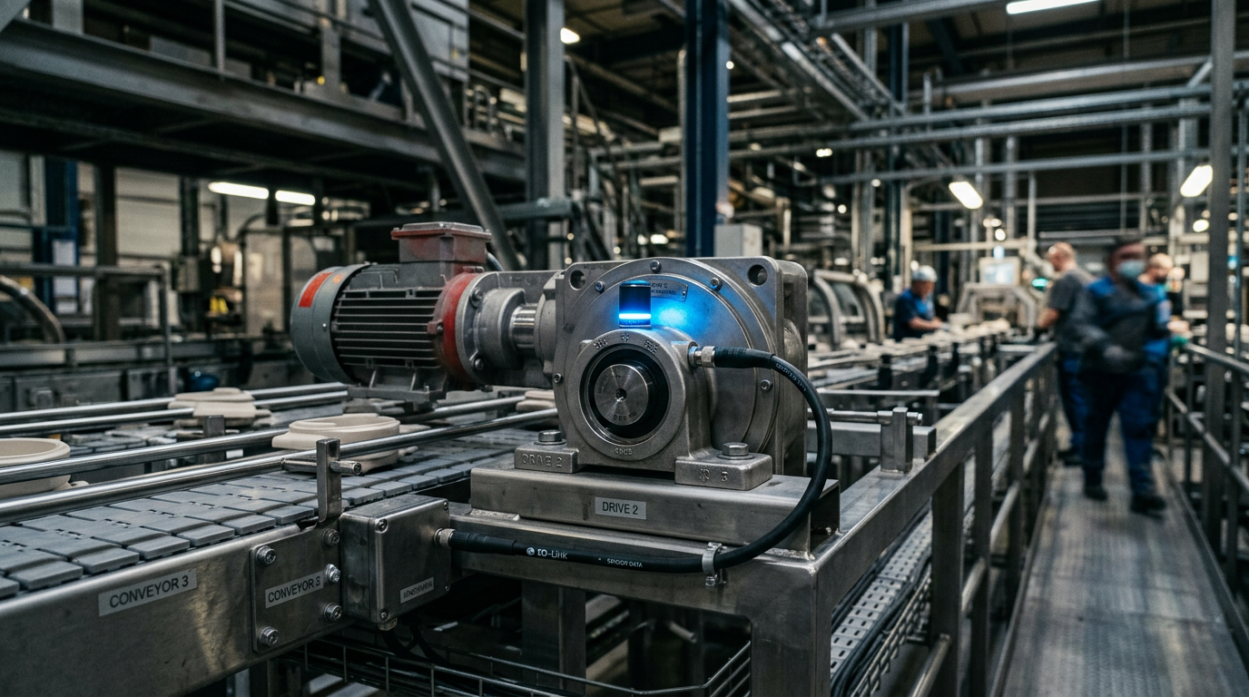
Predictive maintenance for conveyor drives utilizes vibration sensors to detect early-stage bearing wear and gear mesh misalignment, typically identifying faults 1.5 to 3 months before catastrophic failure occurs. By monitoring Velocity (mm/s) and Acceleration (g) across specific frequency spectra (typically 10 Hz to 10 kHz), maintenance teams can transition from reactive repairs to data-driven interventions that reduce unplanned downtime by up to 30%.
The Role of Vibration Analysis in Conveyor Reliability
Modular conveyor systems are the arteries of modern production, yet their reliability is often tethered to the health of the drive motor and gearbox. Traditional preventive maintenance—where parts are replaced based on a fixed schedule—often leads to the premature disposal of functional components or, worse, fails to prevent random "infant mortality" failures.
Predictive maintenance (PdM) leverages the principle that every rotating component generates a unique vibration signature. When a bearing develops a micro-pit or a gear tooth experiences eccentric wear, the vibration profile shifts in a measurable way according to ISO 20816-1. By mounting triaxial accelerometers directly on the motor housing and gearbox output shaft, automation engineers can capture "digital fingerprints" of machine health.
Key Metrics for Conveyor Drive Monitoring
To effectively monitor a conveyor drive, sensors must track several distinct variables:
- RMS Velocity (10-1000 Hz): This is the primary indicator of overall machine health, including unbalance, misalignment, and structural looseness.
- Peak Acceleration: Vital for detecting high-frequency impacts associated with early-stage rolling element bearing failures.
- Crest Factor: A ratio of peak to RMS values that helps identify impulsive shocks before they generate significant heat or noise.
- Temperature: Often integrated into modern vibration sensors to provide a secondary data point for confirming friction-related issues.
Deploying Vibration Sensors on Modular Systems
When integrating these sensors into a modular conveyor layout, placement is critical. For a standard drive assembly, sensors should be placed as close to the load zone as possible. In high-performance systems like those designed by Easy Conveyors, the modular nature of the drive mounting allows for easy access to the bearing housings, which are the optimal attachment points.
Communication Architecture: From Sensor to Edge
Modern industrial automation has moved beyond simple "vibration switches" to intelligent IO-Link sensors. These devices don't just output an analog 4-20mA signal; they provide pre-processed FFT (Fast Fourier Transform) data.
- Level 1: The Sensor: Captures raw time-waveform data.
- Level 2: The Gateway/PLC: Aggregates data from multiple drives. A VFD or PLC can often perform basic thresholding.
- Level 3: Edge Computing/Cloud: Uses machine learning algorithms to compare current vibration data against historical baselines and ISO standards like ISO 10816.
| Performance Tier | Monitoring Method | Fault Detection Window | Typical Cost |
|---|---|---|---|
| Reactive | Visual & Audible Check | < 24 Hours | Low (OPEX high) |
| Preventive | Calendar-based replacement | N/A | Medium |
| Condition-Based | RMS Vibration Thresholds | 1 - 2 Weeks | Medium |
| Predictive | FFT Spectral Analysis & AI | 1 - 4 Months | High (ROI < 12mo) |
Identifying Common Conveyor Drive Failures
Vibration analysis allows technicians to "see" inside the gearbox without a teardown. Each mechanical fault resonates at a specific frequency relative to the shaft's rotational speed (RPM).
Bearing Degradation
Bearings typically fail in four stages. Stage 1 involves ultra-high frequency vibrations (20kHz+) detectable only by specialized ultrasonic sensors. By Stage 3, the vibration becomes evident in the standard 10Hz-1kHZ range, showing up as "sidebands" around the bearing's fundamental defect frequencies. This is the "sweet spot" for replacement, where the motor is still functional but the end of life is predictable.
Gearbox Misalignment and Backlash
In modular systems, the connection between the motor and the conveyor drive shaft is a common point of stress. Misalignment typically manifests as a high vibration peak at exactly 2x the shaft speed (2x RPM). If the teeth are worn, a "gear mesh frequency" (GMF) will appear, surrounded by sidebands that grow in amplitude as the wear worsens.
Easy Conveyors stocks the industrial automation discussed here — ready to ship across Europe.
Integration with Industrial Control Systems
For a predictive maintenance strategy to be effective, it must be integrated into the broader industrial automation stack. Utilizing IEC 61131-3 compliant programming, engineers can set "Warning" and "Critical" alarms directly in the PLC.
For instance, an IE3 efficiency motor (IEC 60034-30-1) running at variable speeds requires a "dynamic threshold" strategy. Because vibration amplitude naturally increases with RPM, the monitoring system must adjust its alarm limits based on the current frequency output of the VFD. This prevents false positives when the conveyor ramps up during peak production hours.
Synergy with Other Components
Vibration monitoring is most powerful when combined with other data streams. Pairing vibration data with "VFD soft-start tuning" metrics—such as current draw and torque ripple—provides a holistic view of the system. If vibration increases while current draw remains stable, the issue is likely a mechanical misalignment. If both spike, the motor may be experiencing electrical winding stress or an over-tensioned belt.
Implementation Challenges and Solutions
The primary hurdle in conveyor PdM is the "noise" generated by the conveyor belt and the product itself. In parcel sortation or heavy-duty pallet handling, the impact of goods can mask subtle bearing vibrations.
- Solution 1: Time-Synchronous Averaging (TSA). This technique filters out random noise by averaging vibration signals over multiple revolutions of the shaft, highlighting the periodic signals related to the drive internals.
- Solution 2: Proximity Sensing. Using a photo-eye to trigger vibration capture only when the conveyor is empty ensures a clean baseline measurement.
Future-Proofing with AI and Machine Learning
As we move toward Industry 4.0, the "digital twin" concept becomes reality. By feeding vibration data into a cloud-based ML model, the system learns the unique "normal" state of every single drive in a facility. This is particularly useful for complex layouts where "hygienic wash-down design" requirements might limit sensor placement to less-than-ideal locations. AI can compensate for these suboptimal mounting points by identifying patterns in the degraded signal.
Maintenance managers can now receive a push notification on their mobile device: "Drive Motor 402 in Hall B shows a 15% increase in non-synchronous vibration. Estimated bearing failure in 42 days. Order replacement Part #XYZ now." This level of foresight transforms the maintenance department from a cost center into a strategic asset that guarantees uptime. Conveyor systems are no longer just mechanical tracks; they are intelligent, self-diagnosing networks. Applying vibration sensors to conveyor drives is the single most effective way to ensure those networks never stop moving.
Frequently Asked Questions
Where is the best place to mount a vibration sensor on a conveyor drive?
For conveyor drives, the motor bearing housing and the gearbox output shaft housing are the most critical points. Sensors should be mounted as close as possible to the load zone to capture accurate rotational data.
What frequency range is required for conveyor vibration monitoring?
Standard sensors typically monitor from 10 Hz up to 1,000 Hz or 10,000 Hz. For early-stage bearing detection, high-frequency acceleration monitoring (up to 20kHz) is preferred, while general health is monitored in the lower range.
Can I use temperature sensors instead of vibration sensors?
While both are valuable, vibration sensors detect mechanical wear (bearings/gears) much earlier. Temperature sensors usually trigger once friction is high enough to cause heat, which often means the component is already near catastrophic failure.
Can vibration monitoring work on variable speed conveyors?
Yes, but with caveats. You must implement dynamic thresholds because vibration levels naturally increase with speed. Integration with the VFD via IO-Link allows the monitoring system to adjust alarm levels based on current RPM.