Predictive Maintenance with Vibration Sensors on Conveyor Drives
Learn how vibration sensors on conveyor drives predict failures, reduce downtime by up to 50%, and transition your facility to data-driven maintenance.
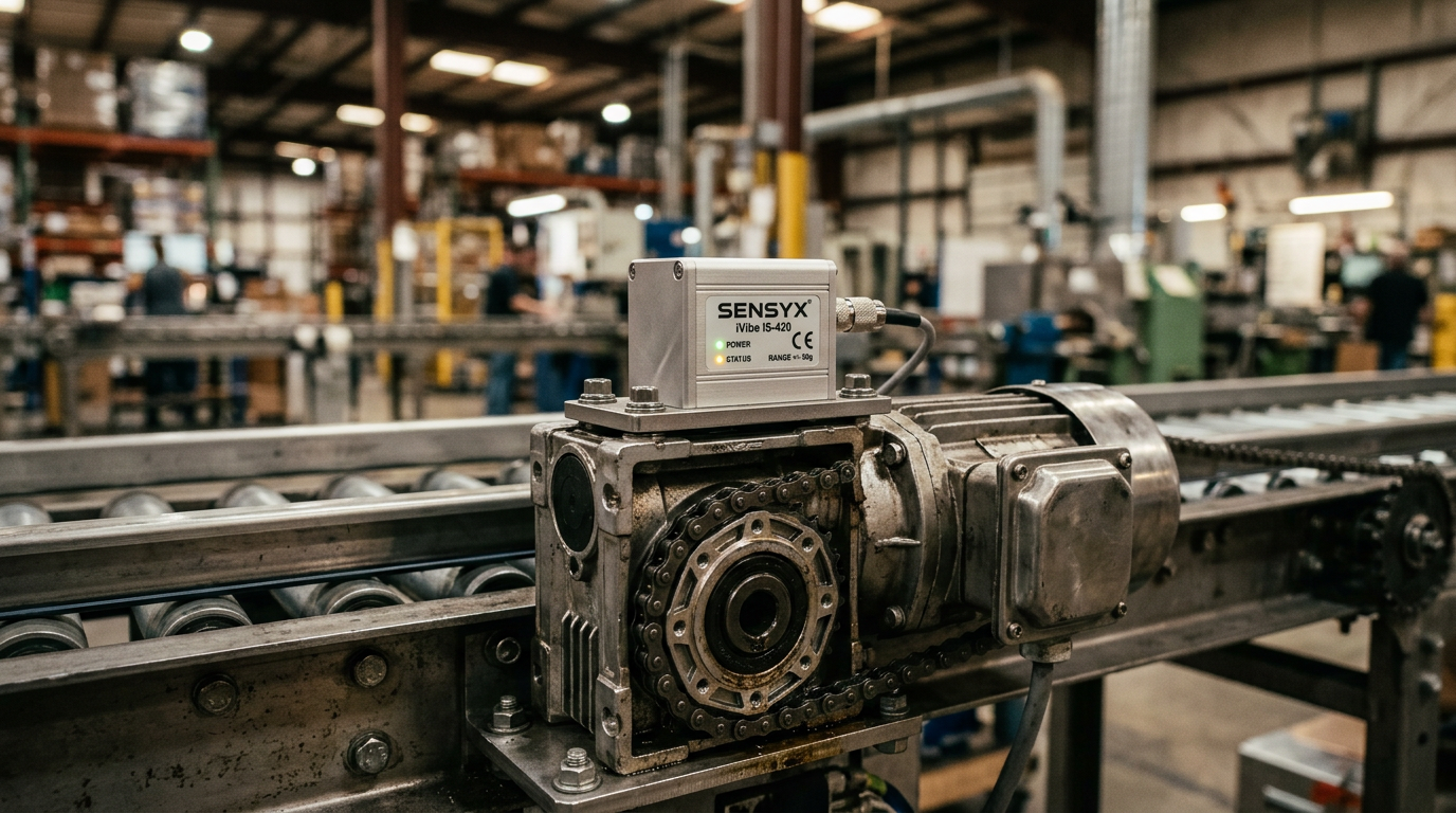
Predictive maintenance using vibration sensors on conveyor drives typically reduces unplanned downtime by 30% to 50% by detecting early-stage bearing wear and gear mesh misalignments up to months before physical failure occurs. By monitoring Velocity (RMS) and Acceleration (Peak) against ISO 20816-1 standards, maintenance teams can transition from reactive "run-to-fail" models to data-driven intervention windows.
Predictive maintenance (PdM) has evolved from a luxury for heavy machinery into a necessity for high-throughput logistics and manufacturing. Within modular conveyor systems, the drive unit—comprising the motor and gearbox—is the most critical point of failure. Vibration sensors, often integrated with PLC systems or IoT gateways, serve as the "stethoscope" for these mechanical hearts.
The Physics of Vibration Monitoring in Conveyor Drives
Every rotating component in a conveyor drive generates a unique vibration signature. When a motor is brand new and perfectly aligned, these vibrations are minimal and periodic. However, as defects develop, the energy released through vibration increases in specific frequency bands.
Velocity vs. Acceleration
In the context of conveyor health, we monitor two primary metrics:
- Velocity (mm/s RMS): This is the best indicator of overall "severity." It helps detect low-frequency issues like unbalance, structural looseness, and misalignment between the motor and the drive roller.
- Acceleration (g): This is used to detect high-frequency impacts. It is essential for identifying early-stage bearing fatigue and gear tooth pitting.
For standard industrial conveyor drives, mechanical health is often graded according to ISO 10816-3, which classifies machines by size and mounting type (rigid vs. flexible).
Key Failure Modes Detected by Sensors
Vibration analysis allows engineers to squint into the future of their hardware. By deploying triaxial accelerometers on the drive housing, the following issues are identified:
- Bearing Degradation: Bearings follow a predictable "four-stage" failure curve. Sensors can detect Stage 1 (ultrasonic noise) long before the bearing generates heat or audible squealing.
- Gearbox Misalignment: If the drive shaft is not perfectly perpendicular to the conveyor frame, it creates axial vibration. This leads to uneven wear on modular belts and premature failure of the drive sprockets.
- Imbalance: Debris buildup on a drum motor or a bent shaft in a gearmotor will show up as a high-amplitude signal at the 1x running speed frequency.
- Resonance: If the conveyor's structural frame vibrates at the same frequency as the motor’s rotational speed, it can lead to weld cracks and fastener loosening.
Integration Strategy: From Sensor to Edge
The hardware architecture for a vibration-based PdM system usually follows one of three paths:
1. The PLC-Integrated Approach
For plants already using advanced automation, vibration sensors with 4-20mA or IO-Link outputs are wired directly into the main PLC. The PLC logic compares the real-time value against a hardcoded threshold. While simple, this lacks the "Frequency Domain" (FFT) analysis depth needed for precise diagnostics.
2. The IoT Wireless Gateway
Battery-powered Bluetooth or LoRaWAN sensors are mounted on the drive. These transmit data to a local gateway and then to a cloud-based dashboard. This is ideal for retrofitting existing lines where running new cables is cost-prohibitive.
3. The Edge Analytics Controller
Specialized hardware performs High-Speed Fourier Transforms (FFT) at the conveyor. Instead of sending raw data to the cloud, it only sends "Health Scores." Easy Conveyors advocates for integrated modular designs where drive components are easily accessible for sensor mounting, ensuring that the structural integrity of the module does not dampen the vibration signals required for accurate reading.
Easy Conveyors stocks the industrial automation discussed here — ready to ship across Europe.
Comparing Maintenance Strategies
The shift from preventive (time-based) to predictive (condition-based) maintenance significantly alters the Total Cost of Ownership (TCO).
| Feature | Reactive Maintenance | Preventive (Scheduled) | Predictive (Vibration) |
|---|---|---|---|
| Trigger | Component Failure | Calendar/Hours | Vibration Threshold |
| Downtime | Unplanned & Long | Planned & Moderate | Minimal/Scheduled |
| Spare Parts | Rush Ordered | Stocked in Bulk | Just-in-Time |
| Labor Cost | High (Overtime) | Medium | Optimized |
| Typical ROI | N/A | 12-18 Months | 6-12 Months |
Sizing and Selecting Vibration Sensors
When selecting a sensor for a conveyor drive, several technical factors must be considered:
Frequency Range (Bandwidth)
Most conveyor motors run at 1,500 to 3,000 RPM (25-50 Hz). However, to catch bearing defects, the sensor needs a frequency range up to at least 10 kHz. Low-cost sensors often cut off at 1 kHz, missing early-stage failures.
Sensitivity and Range
For standard gearmotors, a sensitivity of 100 mV/g is the industry gold standard. For high-speed sorters or heavy-duty pallet conveyors, the "g-range" (dynamic range) should be at least ±50g to allow for high-impact shocks without clipping the signal.
Environmental Protection
Conveyor drives in food processing or pharmaceutical environments require IP69K-rated sensors that can withstand high-pressure washdowns and caustic cleaning agents. In these environments, hygienic design (consistent with EHEDG guidelines) is as important as the electronic accuracy.
Advanced Data Analysis: Enveloping and FFT
To truly maximize the value of vibration monitoring, maintenance teams should look beyond simple RMS values.
- Fast Fourier Transform (FFT): This converts the time-signal into a frequency spectrum. If a peak appears at exactly the "Ball Pass Frequency" of the bearing, you know exactly which part is failing.
- Time Waveform (TWF): This shows the raw vibration over time. It is used to identify "clunking" or intermittent impacts that might be averaged out in an RMS reading.
Integrating these signals with other parameters, such as VFD soft-start tuning or drum motor selection, allows for a holistic view of the system's stress levels. For instance, if vibration levels rise only during acceleration phases, it may indicate a need to adjust the VFD ramp-up parameters to avoid mechanical resonance.
Implementation Hurdles and Best Practices
The most common failure in PdM implementation is "Data Fatigue." Collecting millions of data points without an actionable alert system leads to sensors being ignored.
- Baseline First: Never set alarm thresholds based on a manual. Always run the conveyor for 24-48 hours under normal load to establish a "normal" baseline.
- Mounting Matters: Sensors must be stud-mounted or attached with industrial epoxy to the bearing housing. Magnetic mounts are only for temporary "walk-around" checks; they filter out high-frequency signals.
- Cross-Reference with Temperature: Vibration sensors are most powerful when paired with PT100 temperature probes. A rise in vibration followed by a rise in temperature is a 99% certain indicator of imminent bearing seizure.
By treating vibration data as a core part of the automation stack, plant managers can ensure their conveyors—the arteries of the modern factory—never stop flowing unexpectedly. Use these insights during hygienic wash-down design cycles to ensure sensors are located where they are most effective yet protected from the environment.
Frequently Asked Questions
What vibration levels are considered 'dangerous' for a conveyor motor?
For most conveyor drives, Velocity (RMS) should be monitored against ISO 10816-3. Generally, levels below 2.8 mm/s are considered 'good,' while levels exceeding 7.1 mm/s for small machines or 11 mm/s for large machines indicate 'unacceptable' condition.
What is the typical frequency range needed for bearing monitoring?
Standard vibration sensors (accelerometers) typically cover 10 Hz to 10 kHz. Advanced 'High-Frequency' sensors used for early-stage bearing detection can monitor up to 25 kHz or higher to capture ultrasonic stress waves.
Should I use wireless or wired sensors for my conveyor line?
IoT/Wireless sensors are easier to retrofit but require battery management and have slower sampling rates. Wired IO-Link sensors offer real-time data and higher resolution for FFT analysis but involve higher installation costs.
Can vibration sensors detect a belt jam?
While vibration is the leading indicator, monitoring motor current (Amperage) and bearing housing temperature provides a 'triple-check.' An increase in vibration alongside a spike in current often signals a mechanical jam or heavy belt overload.
Are vibration sensors compatible with wash-down environments?
Yes, provided the sensor is IP69K rated and the data cable or wireless housing is resistant to the specific chemicals used in your facility. Stainless steel housings are mandatory in these environments.