Maximizing Uptime: Predictive Maintenance with Vibration Sensors on Conveyor Drives
Discover how vibration sensors and FFT analysis transform conveyor drive maintenance, reducing downtime by 50% through early detection of bearing and gear faults.
In modern automated facilities, predictive maintenance with vibration sensors on conveyor drives reduces unplanned downtime by up to 50% by identifying bearing wear and gear misalignment at the micron level before thermal failure occurs. By monitoring frequency ranges between 10 Hz and 10 kHz, operators can distinguish between normal mechanical resonance and specific fault signatures like inner-race bearing defects or gear tooth chipping.
The Shift from Reactive to Predictive Maintenance
Traditionally, conveyor maintenance followed a "run-to-fail" or a rigid time-based schedule. The former leads to catastrophic production halts, while the latter often results in the premature replacement of perfectly functional components. Predictive maintenance (PdM) leverages Industrial Internet of Things (IIoT) sensors to monitor the actual health of the drive system in real-time.
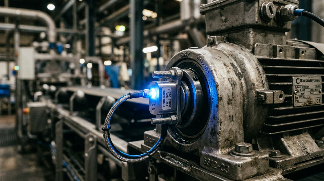
For a conveyor drive—typically a combination of an electric motor and a gearbox—vibration analysis acts as an early warning system. While a technician might notice a hot motor or a loud grinding noise, these are lagging indicators; the damage is already done. Vibration sensors detect high-frequency oscillations that signal the onset of degradation weeks or even months before the component fails.
Key Vibration Metrics for Conveyor Drives
When selecting sensors for conveyor drives, engineers must look at three primary metrics:
- Velocity (RMS): Measured in mm/s, this is the best indicator of overall machine health and general looseness or unbalance. Most ISO 10816 standards categorize machine health based on these RMS values.
- Acceleration: Measured in g’s, acceleration is critical for detecting high-frequency faults such as bearing race defects or gear meshing issues.
- Displacement: Measured in microns, this is typically used for low-speed applications to detect shaft wobble or structural instability.
For standard modular systems, such as those designed by Easy Conveyors, integrating these sensors at the motor non-drive end and the gearbox output shaft provides a comprehensive view of the entire drivetrain's mechanical integrity.
Identifying Specific Fault Signatures
Vibration analysis is not just about the volume of the noise, but the frequency at which it occurs. Different mechanical failures have distinct "fingerprints" in the frequency domain (FFT analysis).
Bearing Failure Stages
Bearings are the most common point of failure in conveyor drives. Vibration sensors can track the four stages of bearing failure:
- Stage 1: High-frequency ultrasonic noise (250-500 kHz). Undetectable by ear or touch.
- Stage 2: Increased vibration at natural frequencies of bearing components (500 Hz - 2 kHz).
- Stage 3: Appearance of fundamental defect frequencies (BPFO, BPFI) and their harmonics.
- Stage 4: Broad-spectrum noise floor rise; the bearing is nearing catastrophic seizure.
Misalignment and Unbalance
Misalignment usually manifests as a strong vibration peak at exactly 2x the shaft's rotational speed (2x RPM). In contrast, an unbalanced pulley or motor rotor will show a dominant peak at 1x RPM. Distinguishing between these allows maintenance teams to decide whether to simply re-balance a component or perform a precision laser alignment.
Comparing Sensor Technologies for Conveyor Monitoring
| Feature | Piezoelectric Accelerometers | MEMS Sensors | Ultrasonic Sensors |
|---|---|---|---|
| Frequency Range | Up to 20 kHz | Up to 6 kHz | 20 kHz to 100 kHz |
| Durability | High (Industrial) | Moderate | High |
| Cost Tier | Premium | Economical | Mid-range |
| Output Type | Analog (4-20mA/IEPE) | Digital (IO-Link/MQTT) | Analog/Digital |
| Best Use Case | Precision Gearboxes | Standard Belt Motors | Early Bearing Detection |
Easy Conveyors stocks the industrial automation discussed here — ready to ship across Europe.
Integrating Sensors into the Automation Layer
Modern predictive maintenance doesn't require a vibration expert on-site 24/7. IIoT gateways collect data from sensors (often via IO-Link or Modbus TCP) and push it to the cloud or an on-premise Edge controller.
Implementing VFD soft-start tuning can significantly reduce the mechanical stress captured by these sensors during start-stop cycles. Furthermore, when combined with drum motor selection data, software can normalize vibration readings based on load and speed, preventing false alarms when the conveyor is running at high speeds or under maximum capacity.
Practical Implementation: The "Traffic Light" System
For operations managers, the raw data is less important than the "actionable insight." Most PdM platforms translate complex FFT data into a simple dashboard:
- Green: Normal operation within ISO 10816 limits.
- Yellow: Warning. Schedule an inspection within the next 14 days.
- Red: Critical. Immediate intervention required to prevent secondary damage to the drive shaft or belt.
By focusing on "Time to Failure" (TTF) metrics, plants can move toward a hygienic wash-down design philosophy where even the sensors are IP69K rated, ensuring that the predictive capabilities remain intact even in the harshest food-processing environments.
Economic Impact and ROI
The ROI for vibration monitoring on conveyor drives is typically realized within 12 to 18 months. Consider the cost of one hour of downtime in a high-speed sortation center, which can exceed €50,000. If a €500 sensor prevents a single four-hour outage, the system has paid for itself many times over. Additionally, by avoiding catastrophic failures, companies reduce "secondary damage"—for example, a seized bearing that snaps a drive chain or melts a plastic modular belt.
Future Trends: AI and Edge Analytics
As we move further into the decade, we are seeing the rise of "Smart Sensors" that perform FFT analysis within the sensor housing itself. Instead of sending streams of raw data to the PLC, the sensor only communicates the "health score." This reduces the bandwidth requirements on industrial networks and allows for faster response times. Machine learning models are also becoming better at filtering out the background noise of the factory floor, allowing for even more precise detection of micro-fractures in drive components.
Frequently Asked Questions
Where should vibration sensors be placed on a conveyor drive?
Standard piezoelectric or MEMS vibration sensors are usually mounted on the bearing housings of the motor (drive and non-drive ends) and the gearbox output shaft for total coverage.
Why use vibration sensors instead of simple temperature monitoring?
Vibration sensors detect 'hidden' mechanical faults like bearing fatigue and gear misalignment weeks before they become audible or cause temperature spikes.
Can vibration sensors be used in hygienic food-grade environments?
Yes, many sensors are now available with IP69K ratings and stainless steel housings, making them suitable for EHEDG and FDA-compliant wash-down zones.
What is the best communication protocol for industrial vibration sensors?
IO-Link is the preferred protocol as it provides not just the vibration data, but also device status and easy parameterization through the PLC.
Is RMS velocity enough for comprehensive drive diagnostics?
No, high-frequency acceleration data (g) is required to detect early-stage bearing wear, while velocity (mm/s) is better for detecting unbalance.