Maximizing Uptime: Predictive Maintenance with Vibration Sensors on Conveyor Drives
Optimize uptime with predictive maintenance. Learn how vibration sensors on conveyor drives detect faults early, preventing costly unplanned downtime in manufacturing.
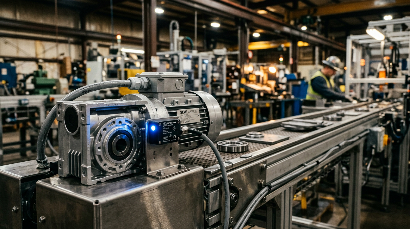
Predictive maintenance with vibration sensors on conveyor drives is a condition-monitoring strategy that uses high-frequency data collection to identify mechanical anomalies before they lead to catastrophic equipment failure. By analyzing the velocity and acceleration profiles of motors and gearboxes, maintenance teams can transition from reactive repairs to data-driven scheduling, significantly reducing unplanned downtime in industrial environments.
Key Takeaways
- Early Detection: Vibration sensors detect bearing wear and gear misalignment weeks before audible noise or heat generation occurs.
- Reduced Total Cost of Ownership: Moving from preventive to predictive maintenance can reduce maintenance costs by 25-30%.
- ISO 10816 Compliance: Standards provide the baseline for what constitutes "healthy" vibration levels across different machine classes.
- Data Integration: Modern IO-Link and wireless sensors allow for seamless integration with PLC systems and cloud analytics.
The Physics of Vibration in Conveyor Drives
Every rotating component in a conveyor drive system—the motor shaft, the cooling fan, the gearbox pinions, and the drive sprocket—generates a unique frequency signature. In a healthy system, these vibrations are low-amplitude and consistent. However, as components degrade, they generate specific "fault frequencies."
Predictive maintenance relies on detecting these shifts early. For example, a failing ball bearing produces a distinct high-frequency peak (known as the Ball Pass Frequency) long before the motor housing becomes hot to the touch. By the time a human operator notices a conveyor is "running loud," the damage is often extensive enough to require a full drive replacement rather than a simple bearing swap.
Acceleration vs. Velocity vs. Displacement
When implementing vibration monitoring, it is critical to understand what is being measured:
- Displacement: Measured in mils or microns; used for low-frequency vibration and structural issues.
- Velocity: Measured in mm/s or inches/s; the most common metric for general machine health (ISO 10816).
- Acceleration: Measured in g; critical for detecting high-frequency bearing failures and gear mesh issues.
Critical Components Monitored by Vibration Sensors
Integrating sensors onto a conveyor system requires strategic placement. You cannot simply mount a sensor anywhere on the frame and expect actionable data; the sensor must be as close to the vibration source as possible.
Motor Bearings (Drive End and Non-Drive End)
The drive end (DE) bearing of the motor bears the highest load, making it the primary point of failure. Sensors mounted here detect misalignment with the gearbox and internal electrical discharge machining (EDM) caused by Variable Frequency Drive (VFD) usage.
Gearbox Housing
In modular conveyor systems, gearboxes often operate under varying loads. Vibration analysis can identify chipped gear teeth or eccentric shafts. For complex layouts, Easy Conveyors provides modular components designed for high accessibility, making the mounting of these sensors straightforward even in compact automation cells.
Drive Pulley and Sprockets
While the motor and gearbox are the "heart," the drive pulley or sprocket is where the power meets the belt. Vibration sensors here can detect "belt slap" or uneven tensioning that might lead to premature wear of the conveyor modules.
Technical Implementation: Wired vs. Wireless Sensors
The choice of hardware architecture depends on the scale of the facility and the criticality of the conveyor line.
1. IO-Link Sensors (Wired)
For high-speed sortation or mission-critical automotive lines, wired IO-Link sensors are the gold standard. They provide:
- Real-time data transmission to the PLC.
- Integration with existing automation logic (e.g., triggering a "Warning" light on the HMI).
- High sampling rates (up to several kHz) for detailed spectral analysis.
2. LoRaWAN and Bluetooth Sensors (Wireless)
For expansive distribution centers where running cables is cost-prohibitive, wireless sensors are preferred. These devices are battery-powered and wake up at set intervals (e.g., every 30 minutes) to take a "snapshot" of machine health. They are ideal for monitoring long stretches of conveyors where instantaneous data isn't required but long-term trends are essential.
Analyzing the Data: FFT and Time-Waveform
Collecting data is only half the battle; the "predictive" part comes from signal processing.
- Fast Fourier Transform (FFT): This process converts the complex vibration signal from the time domain (amplitude over time) to the frequency domain (amplitude over frequency). This allows engineers to see exactly which component is failing. If a spike appears at 58 Hz, and the motor runs at 3480 RPM (58 Hz), the issue is likely unbalance.
- Root Mean Square (RMS): This provides an overall health score. An increasing RMS value indicates that the machine is deteriorating generally, even if a specific fault hasn't been identified yet.
Easy Conveyors stocks the industrial automation discussed here — ready to ship across Europe.
ISO 10816: The Benchmark for Condition Monitoring
To avoid "alarm fatigue," engineers use the ISO 10816 standard to set thresholds. This standard categorizes machines by size and mounting (rigid vs. flexible). For most conveyor drives (Class I or Class II):
- 0.0–1.1 mm/s: Good/New condition.
- 1.1–2.8 mm/s: Satisfactory.
- 2.8–4.5 mm/s: Unsatisfactory (plan maintenance).
- >4.5 mm/s: Unacceptable (potential for immediate failure).
Transitioning from Preventive to Predictive Maintenance
Most factories currently operate on a preventive schedule—replacing bearings every 12 months or greasing motors every 500 hours. While better than waiting for a break, this is inefficient. You may be discarding perfectly good components or, conversely, a bearing might fail at month 10, leaving you with 2 months of unplanned downtime.
Predictive maintenance with vibration sensors allows for Condition-Based Maintenance (CBM). You only perform the work when the data indicates it is necessary. This reduces spare parts inventory costs and prevents human-induced failures (such as over-greasing) during unnecessary maintenance windows.
Challenges and Common Failure Modes
Implementing a vibration program is not without hurdles. Common pitfalls include:
- Incorrect Mounting: Using magnets on curved surfaces or plastic housings dampens the signal. Sensors should be stud-mounted or glued to flat, machined metallic surfaces.
- Ambient Noise: In large bottling plants, the vibration from one conveyor can travel through the floor and affect the sensor on a neighboring machine. Advanced "cross-talk" filters are required.
- VFD Interference: Variable Frequency Drives change the motor speed, which changes the fault frequencies. Smart systems must be linked to the VFD to know the current RPM before interpreting the vibration data.
Future Outlook: AI and Edge Analytics
By late 2026, we are seeing a massive shift toward "Edge AI." Instead of sending raw vibration data to a cloud server, the sensor itself contains a small microcontroller that performs the FFT locally. It only sends an alert when it detects a specific failure pattern, such as "Inner Race Bearing Wear detected: 85% confidence." This drastically reduces bandwidth requirements and allows for faster response times in highly automated environments.
Frequently Asked Questions
What are the ISO 10816 vibration standards for conveyor motors?
Small conveyor drives typically fall under Class I (small machines up to 15 kW) or Class II (medium machines up to 75 kW). According to ISO 10816, vibration levels below 1.1 mm/s are considered good, while levels exceeding 4.5 mm/s usually require immediate attention.
Where is the best place to mount a vibration sensor on a conveyor drive?
For the most accurate data, sensors should be mounted directly on the bearing housing of the motor or gearbox. They should be placed in the radial direction (perpendicular to the shaft) for most faults, or the axial direction (parallel to the shaft) to detect thrust-load issues or misalignment.
How much lead time does vibration monitoring give before a total failure?
Vibration analysis can often detect bearing or gear degradation 4 to 8 weeks before failure. This provides a significant window to order parts and schedule repairs during a planned weekend shutdown rather than stopping production mid-shift.
Can vibration sensors work on variable-speed conveyors?
Yes. Since vibration frequencies change with motor speed, the monitoring system must be integrated with the VFD or an encoder. This allows the software to normalize the data based on the current RPM to prevent false alarms.
Is vibration monitoring better than temperature monitoring for drives?
While temperature sensors (thermocouples) are useful, they are 'late-stage' indicators. By the time a gearbox or motor gets hot, the internal damage is already significant. Vibration sensors detect the microscopic changes that lead to heat, offering a much earlier warning.
Sources & references
- [1]ISO 20816-1:2016 - Mechanical vibration — Measurement and evaluation of machine vibration
- [2]Condition Monitoring Systems for Drive Engineering
- [3]Predictive Maintenance for Material Handling and Conveyor Systems
- [4]Vibration Sensors for Machine Condition Monitoring
- [5]Vibration Monitoring (Wikipedia)